 |
| Sketch: focusing on the right hand side of the image - an arm mechanism that will have the abilities as stated above. |
Friday, 30 September 2011
Friday, 30th of September 2011 - Servo motor arm
The following image shows a possible design for the arm that will attach to the servo-motor to allow it to rotate, knock the wedge in to release gas, as well as spring back an forth to reduce breakage to the mechanism:
Other options for the arm include using only an extension spring as the arm to allow flexibility and force applications. Or solid materials, depending on how the wedge is designed.
Friday, 30th of September 2011 - Control of flame output
Because we will now be needing to control how many flames are active we will need a device that is able to actively and easily "knock on- and knock off" using the already designed gas release mecahnism:
Gas release mechanism(link)
As this is applying a principal of using a lever to "knock" a wedge into place - we will need to use something that can control what a which lever it is pressing.
Such a device can be a servo-motor: (this video shows the function of a servo motor)
Servo motors have the ability to rotate to specific angles, both clockwise and counter-clockwise. This can be applied in our gas release mechanism in a way that each gas release mechanism will have a specific position in the ring to which the servo motor can rotate too:
 |
| Sketch: Servo motor positioning |
The sketch shows how the servo motor might rotate from one position to another from the control of the Arduino circuit board. The servo motor will have an arm attached to in that can spin around with the shaft and knock the wedges into place to release the gas.
Tuesday, 27 September 2011
Tuesday, 27th of September 2011 - Using the heat from the flames to create motion
From previous meetings with the group, we had explored the different methods of creating this motion through the use of the flame itself. From the original concept(link), motion was a direct derivative of the flames and heat. Ergo, by losing heat at one end, the candle would rise, and vice-versa.
Several concepts were explored: eg.
Several concepts were explored: eg.
...Horizontal Motion...
...Vertical Motion...
...Spinning...
...Spinning...
...etc...
Though to come to the outcome of spinning motion came from the inspiration of decorative candle pieces.
 |
| Photo: Candle spinning top - decorative |
With the flame at the base of the object the fan shaped spin top is able to rotate as the hot air is drawing in from the environment surrounding the object and forced upwards do to the heat. This will pass the fan and spin it at speeds controllable by how much heat is rising.
Control
Control of the fan/spinning top speed will be easily obtained when implemented with the new "ring of fire" concept. By controlling how many flames are coming out of the flame dial at once, we are able to control the speed of the fan to a certain extent. However, a question to ask from here is how do we control how many flames are active at the one time...?
By utilizing this concept, we take away the need for any wax - consumable, messy etc. Instead we move towards a clean, tangible interactive product.
Monday, 26 September 2011
Monday, 26th of September 2011 - Visual stimulus additions
Through the model exploration a few key components were found that needed to be refined to a point of a higher degree of functionality. Though this can be seen and attributed to the fact that the models are only prototyped crude constructions.. However they do prove the concept very well!
To add to this however, feedback from the tutors suggested that an added visual stimulus is still needed - other than the flame.
Originally the bobbing was suggested to be brought back from the original concept, although it developed to something that spins would suit better to allow for a background movement without too much disturbance to the visual field. This also ties in the the ring of fire that the product is now utilizing.
From this idea more model making will take place to explore how this spinning will occur..
To add to this however, feedback from the tutors suggested that an added visual stimulus is still needed - other than the flame.
 |
| Visual stimulus exploration: This image shows a rough summary of the outcomes of the visual stimulus exploration that took place amongst the team. |
From this idea more model making will take place to explore how this spinning will occur..
Wednesday, 14 September 2011
Wednesday, 14th of September 2011 - Gas Release mechanism
To continue on from the dismantlement of the lighters - a specifically designed mechanism was needed to allow the concept to be applied in a usable way. To make sure the product is easy to use it is not acceptable to simply use lighters in the design. Hence a gas release mechanism is needed to make sure this is possible:
This will be explored further through the use of computer aided design and simulations...
 |
| Sketch: This mechanism will allow a lever to lift on a pivot point allowing as to be released from the valve. The valve will screw into the threaded section and attach to the lever which pivots off the center A-frame extrusion. The wedge mechanism to depress this lever will pivot off of the cylindrical extrusion (bottom-right of top view). This will allow for a simple "knock-on" - "knock-off" way of releasing the gas to create the ring of flames. |
This will be explored further through the use of computer aided design and simulations...
Tuesday, 13 September 2011
Tuesday, 13th of September 2011 - Flame and heat resistance
Because one of the primary components of the design is to feature flame and heat - we must consider the materials in which the product is manufactured (heat resistance/retardant).
It is more than likely that some form of transparent casing will be needed to protect from the open flames. A regular application of Soft Glass should be sufficient as it still takes reasonably high temperatures for it to soften or fuse. - Jim Lesko
It was briefly suggested that we use smoked/frosted glass to create a glow sensation rather than a reflective sensation.

As for the rest of the body/form, it is more a debate of colour and texture..
It is more than likely that some form of transparent casing will be needed to protect from the open flames. A regular application of Soft Glass should be sufficient as it still takes reasonably high temperatures for it to soften or fuse. - Jim Lesko
It was briefly suggested that we use smoked/frosted glass to create a glow sensation rather than a reflective sensation.

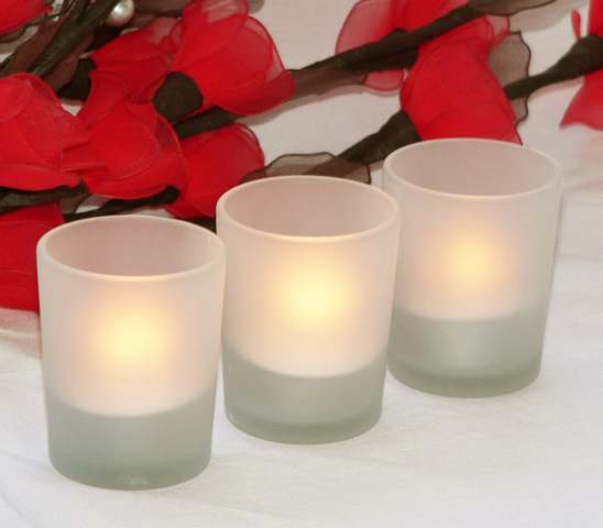 |
| Images: Frosted glass to create a glow feel rather than enhanced reflections through regular glass |
Wednesday, 7 September 2011
Thursday, 7th of September 2011 - Dismantlement of the lighter
To try and figure out how we can use the lighters mechanism we decided to go out and buy a few and pull them apart...
By pulling apart the lighters and experimenting with gas flows and ignition distances, we were able to determine the rings size as well as come up with some configurations for the mechanism themselves. The below video shows how we are able to ignite the next flame off of the previous one...
Making sure that we have the correct distances between the lighters, we can start figuring out how many flames we can use as well as how big the product is going to be - and in particular how it will bit into our chosen scenario and user environment.
 |
| Image: Dismantlement of basic lighter components. Being only press fit in place the top components of the lighter were relatively easy to pry off with the help of a pocket knife. By taking these parts off, we were able to see how the simple action of roll and press was able to create an instant flame. The main component that we were trying to understand was the valve mechanism... |
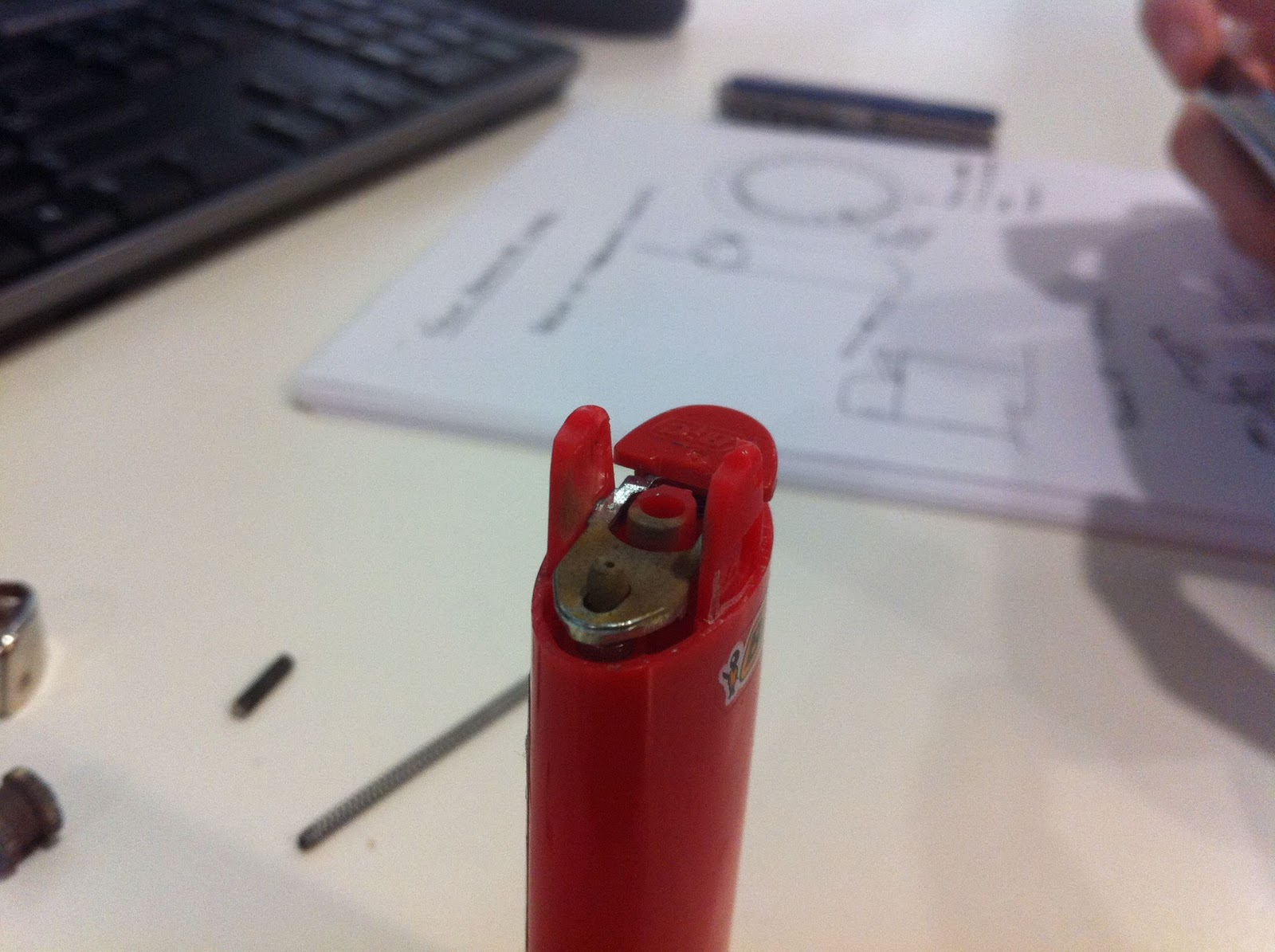 |
| Image: This close up image shows the top of the valve opening as well as the leaver that activates the gas flow. By pressing down on the lever, internal valve line is lifted up to allow gas to pass through a now open channel. By then releasing the lever the opening is shut off and the gas is no longer allowed to flow through through. This valve has been designed so that the appropriate amount of gas is released to allow a flame that is just the right size for ignition aids to other sources. |
 |
| Image: The top parts of the lighter which include the protection housing, flint, flint spark wheel, flint spring and wheel spring. This is basically the assembly that helps create the initial spark to allow flame to be produced from the gas flow coming past the red hot flint material created from a high amount of friction from the flint wheel. |
 |
| Image: This is an exploded view of how a lighter goes together. This lighter is of similar design to the above BIC lighter though this lighter has the ability to be adjusted a lot further than the BIC. The long white extrusion is a fibrous material that allows the butane gas to be absorbed and released in a controlled manner (filter). |
 |
| Image: This is the lever mechanism concept that can be incorporated into the product. There were a few problems which we found with this configuration however. As apposed to the BIC lighter, this cheaper version had most of the materials made out a a polymer that caught on fire - this meant that after leaving lit for more than approx. 1 or 2 minutes, these housings and lever started to heat up, become soft and even catch on fire in some cases. This made us realize the design would have to consider the possibilities of components melting due to flame/heat. |
 |
| Image: The KEY component - the gas release valve. This tiny valve is the key to how these lights work as well as the mechanism in which we wish to use in our ring of first concept. The outer which polymer housing holds a metal pipe which can be pulled up to allow gas to flow through some small holes at its base, which when dropped down are normally closed. |
 |
| Image: The principal of how this concept can work - having turned around the gas release lever, we can begin to see how we can design a simple mechanism to allow the lever to be depressed and in turn release gas , creating flame. |
 |
| Image: Close up of the ring of fire. |
 |
| Image: Ring of fire - the ring has been set up with a specific distance between the lighters of 15mm. This is a median distance that has been trialed to see how fare away a lighter can be before it catches on to the next. We have decided to use this concept as it will save having to install ignition sources (such as piezoelectrical) as each flame source. This way we can light off the previous flame, cutting down on the need for individual ignition while still maintaining the variable progression. |
 |
| Image: Shows how the lever can be positioned the reverse what to still achieve gas release. |
By pulling apart the lighters and experimenting with gas flows and ignition distances, we were able to determine the rings size as well as come up with some configurations for the mechanism themselves. The below video shows how we are able to ignite the next flame off of the previous one...
Making sure that we have the correct distances between the lighters, we can start figuring out how many flames we can use as well as how big the product is going to be - and in particular how it will bit into our chosen scenario and user environment.
Tuesday, 6 September 2011
Wednesday, 6th of September - Ring of fire!
How can we create a variable flame output to project a number of users at the same time, that is constantly progressive in its function and output? The bobbing candle is an excellent concept in connecting two users working together and quite literally burning the candle at both ends - though it is somewhat restricted in its user input by only allowing two people to interact with it. Considering the context for people working on projects collaboratively, it would do well to have the ability for more than 2 or 3 members of the collaborative team to have the power to achieve both input and output in the one device.
A simple geometric is needed to represent a variable amount of people, possibly through representing a percentage of the teams inputs. -
By using a ring of fire that utilizes approximately 20 flames, there is a lot more flexibility in how many people are able to collaborate at the same time. Also to make sure an even spread of distribution during operation, applying the flames as a percentage to represent the team members involved will mean all the flames are utilized regardless of how many people are collaborating. A ring also allows the for the minimum amount area used to how many flames can be produced.
In a normal situation, the principal of using the ring off a gas stove would suffice, although this application requires the individual ignition of each flame. For this reason it was decided the use of gas as an ignition source for the flames would be the best option. With the using gas with a combination of the requirement of needing each flame to be individually lit, each flame will need to be controlled using some kind of valve mechanism.
Individual solenoid valves would work well, allowing us to control each gas line individually through the use of the Arduino circuit boards. Unfortunately due to the cost and size of solenoid valves, they have deemed to be an unsuitable to attempt to control each flame in a progressive state. The next best option was to look at mechanical valve options...
The conventional cigarette lighter uses such a mechanism to release gas past a sparking flint to create instant flame/heat. The use of a similar mechanism to control the individual flames in the product would suit the application.
{Add sketch of how a cigarette light would fit inside the base}
Using this mechanism would cut costs substantially while allowing for a higher level of mechanical design freedom. However, would we be able to stretch the concept so far as to actually use the lighters as the gas supply as well???
The problem with this is that the gas supply/lighters and mechanism becomes a consumable object which needs replacing... How do we keep the mechanism but throw away the individual gas supply and stick with a universal supply????
A simple geometric is needed to represent a variable amount of people, possibly through representing a percentage of the teams inputs. -
 |
| Move from bobbing candle to ring of fire |
In a normal situation, the principal of using the ring off a gas stove would suffice, although this application requires the individual ignition of each flame. For this reason it was decided the use of gas as an ignition source for the flames would be the best option. With the using gas with a combination of the requirement of needing each flame to be individually lit, each flame will need to be controlled using some kind of valve mechanism.
 |
| Simple electric solenoid actuator valve |
 |
| Section: Cigarette lighter gas release mechanism |
{Add sketch of how a cigarette light would fit inside the base}
Using this mechanism would cut costs substantially while allowing for a higher level of mechanical design freedom. However, would we be able to stretch the concept so far as to actually use the lighters as the gas supply as well???
The problem with this is that the gas supply/lighters and mechanism becomes a consumable object which needs replacing... How do we keep the mechanism but throw away the individual gas supply and stick with a universal supply????
Monday, 5 September 2011
Monday, 5th of September 2011 -
The link below will take you to the initial concept video presentation in which the group is choosing to explore:
http://dnb601-senseandsensuality.blogspot.com/2011/08/week-5-concept-presentation-burning.html
From exploring different pathways with the tutors, it seemed we should be looking at some different concepts - one of the key aspects of the design that we wanted to stick with however was the flame/candle side of the idea.
 This concept of using a candle/flame was a crucial feedback medium in the context of the design. One of the main ideas in the design (and many other designs focusing towards intelligent interaction design) is the force of presence in the feedback/output side of the interaction. Controlled flame and in particular candles, bring warmth to the space, allowing most people to feel comfortable in their environment.
However, it is important that in the utilisation of the flame that we enhance the scenario in which the product is placed rather than deter the user from their current activity. This is due to the scenario/context of having multiple users contributing to a singular activity or project..
From here the group has explored various ways of moving away from the bobbing motion of the candle (that can be seen in the initial concept video). Another reason from moving away from this type of feedback is it not only distracts the users from their activities but restricts the number of people that can contribute to the activity... How can we keep the medium of flame and apply it so >3 people can participate in the same activity, with a progressive output?
http://dnb601-senseandsensuality.blogspot.com/2011/08/week-5-concept-presentation-burning.html
From exploring different pathways with the tutors, it seemed we should be looking at some different concepts - one of the key aspects of the design that we wanted to stick with however was the flame/candle side of the idea.

However, it is important that in the utilisation of the flame that we enhance the scenario in which the product is placed rather than deter the user from their current activity. This is due to the scenario/context of having multiple users contributing to a singular activity or project..
From here the group has explored various ways of moving away from the bobbing motion of the candle (that can be seen in the initial concept video). Another reason from moving away from this type of feedback is it not only distracts the users from their activities but restricts the number of people that can contribute to the activity... How can we keep the medium of flame and apply it so >3 people can participate in the same activity, with a progressive output?
Subscribe to:
Posts (Atom)