To try and figure out how we can use the lighters mechanism we decided to go out and buy a few and pull them apart...
 |
| Image: Dismantlement of basic lighter components. Being only press fit in place the top components of the lighter were relatively easy to pry off with the help of a pocket knife. By taking these parts off, we were able to see how the simple action of roll and press was able to create an instant flame. The main component that we were trying to understand was the valve mechanism... |
 |
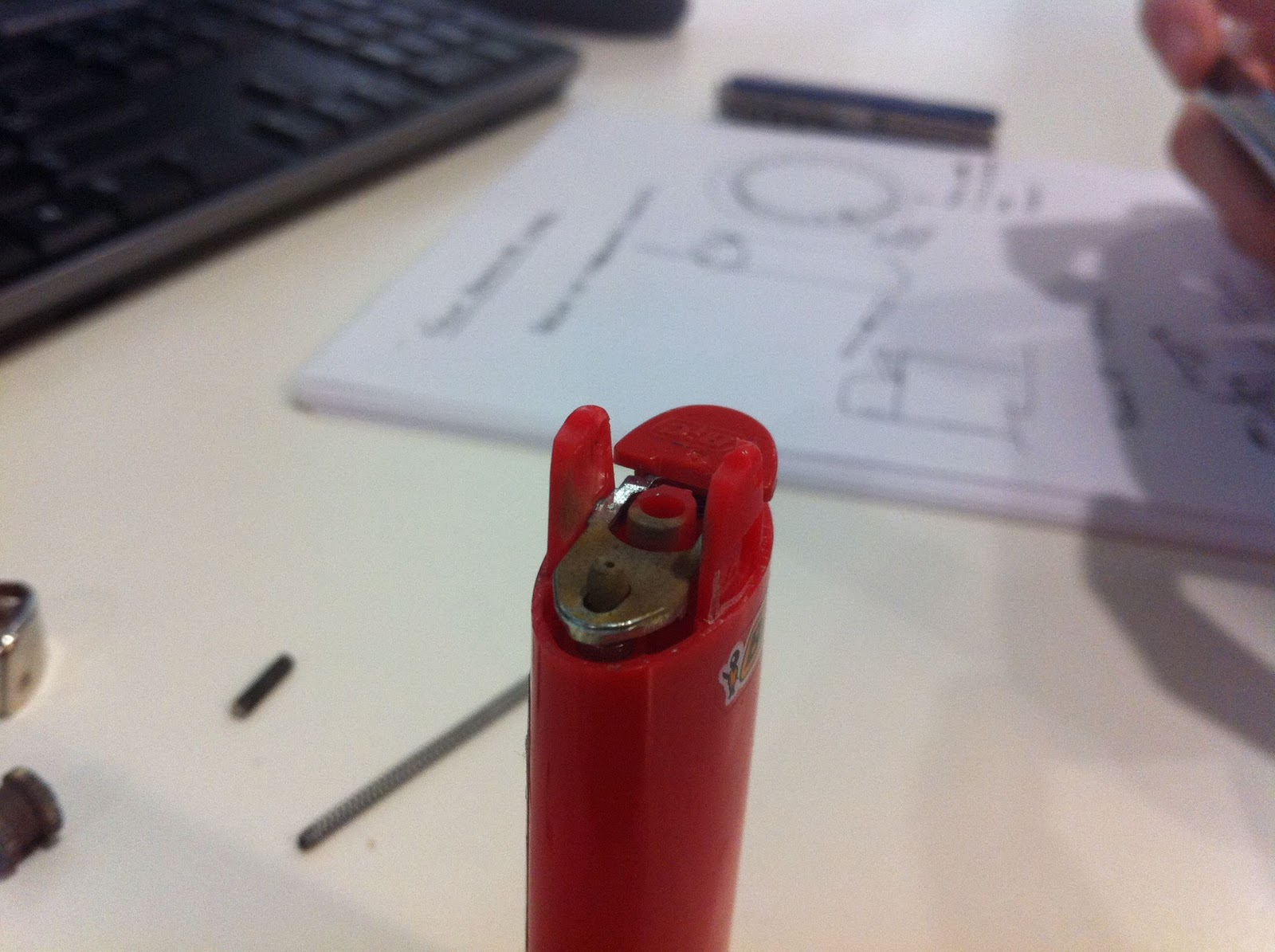
| Image: This close up image shows the top of the valve opening as well as the leaver that activates the gas flow. By pressing down on the lever, internal valve line is lifted up to allow gas to pass through a now open channel. By then releasing the lever the opening is shut off and the gas is no longer allowed to flow through through. This valve has been designed so that the appropriate amount of gas is released to allow a flame that is just the right size for ignition aids to other sources. |
 |
| Image: The top parts of the lighter which include the protection housing, flint, flint spark wheel, flint spring and wheel spring. This is basically the assembly that helps create the initial spark to allow flame to be produced from the gas flow coming past the red hot flint material created from a high amount of friction from the flint wheel. |
 |
| Image: This is an exploded view of how a lighter goes together. This lighter is of similar design to the above BIC lighter though this lighter has the ability to be adjusted a lot further than the BIC. The long white extrusion is a fibrous material that allows the butane gas to be absorbed and released in a controlled manner (filter). |
 |
| Image: This is the lever mechanism concept that can be incorporated into the product. There were a few problems which we found with this configuration however. As apposed to the BIC lighter, this cheaper version had most of the materials made out a a polymer that caught on fire - this meant that after leaving lit for more than approx. 1 or 2 minutes, these housings and lever started to heat up, become soft and even catch on fire in some cases. This made us realize the design would have to consider the possibilities of components melting due to flame/heat. |
 |
| Image: The KEY component - the gas release valve. This tiny valve is the key to how these lights work as well as the mechanism in which we wish to use in our ring of first concept. The outer which polymer housing holds a metal pipe which can be pulled up to allow gas to flow through some small holes at its base, which when dropped down are normally closed. |
 |
| Image: The principal of how this concept can work - having turned around the gas release lever, we can begin to see how we can design a simple mechanism to allow the lever to be depressed and in turn release gas , creating flame. |
 |
| Image: Close up of the ring of fire. |
 |
| Image: Ring of fire - the ring has been set up with a specific distance between the lighters of 15mm. This is a median distance that has been trialed to see how fare away a lighter can be before it catches on to the next. We have decided to use this concept as it will save having to install ignition sources (such as piezoelectrical) as each flame source. This way we can light off the previous flame, cutting down on the need for individual ignition while still maintaining the variable progression. |
 |
| Image: Shows how the lever can be positioned the reverse what to still achieve gas release. |
By pulling apart the lighters and experimenting with gas flows and ignition distances, we were able to determine the rings size as well as come up with some configurations for the mechanism themselves. The below video shows how we are able to ignite the next flame off of the previous one...
Making sure that we have the correct distances between the lighters, we can start figuring out how many flames we can use as well as how big the product is going to be - and in particular how it will bit into our chosen scenario and user environment.


No comments:
Post a Comment