Submission of the folio is due today.
The submission will include:
Blog Links
Project Brief
Product Specification Report
Bill of materials
Unit Costing Sheet
Technical Drawings
A2 presentation boards
All of these files will also be present on a CD submission with inclusions of all of the relevant movies from initial concept, proof of concepts, final prototype, round table discussion presentation, and the final Levi-Mate scenario movie.
Thank you to Marianella, Tim and Yasu for your valuable input into our designs, their processes and our new interactive knowledge.
Monday, 7 November 2011
Thursday, 3 November 2011
Thursday, 3rd of November 2011 - Bill of Materials
Now that the costing has been completed the Bill of Materials can be constructed to give a better idea of parts and their materials and overall costs and weights. 

 |
| Bill of Materials: Levi-Mate |
A bill of materials is a standard in all design and is an essential part of every design process.
Thursday, 3rd of November 2011 - Product costs
As can be seen from the brief it is expected that a 70% profit is required in selling the Levi-Mate. After successful prototyping, 100 units will be produced to be sold at one store as a trial production. If these sales go well unit production will jump to 50 000 units which the following costing is based on:
The above sheet (adapted from Tim Williams upload to DNB303 Manufacturing Technology: Unit Costing Sheet example) shows approximate costings for the Levi-Mate. It uses an overhead rate of $0.57. Note must be taken that a lot of these figures were guesses based off of the QUT unit DNB303 Manufacturing Technology, especially in terms of tooling costs etc. Assuming approximations are correct, the Levi-mate will cost $17.36/unit to manufacture.
Material costs were based on Stienwall Incorporated pricing for polymers (2006). This was more to get an accurate comparison between the material prices rather than prices that may be from different suppliers that have a competitive pricing scheme rather than an internal comparison scheme.
Based on the profit aims the product will then distribute to retail for approx $57.85/unit + GST. This in opinion is too much considering the target market. An aim to produce and distribute to retail at under $50 is an aim that may well be quite easily achievable considering some of the materials (Acrylic-Styrene-Acrylonitrile) costs being very high. If these costs were reduced the price of the Levi-Mate will reduce substantially as well.
 |
| Product Costing Sheet |
Material costs were based on Stienwall Incorporated pricing for polymers (2006). This was more to get an accurate comparison between the material prices rather than prices that may be from different suppliers that have a competitive pricing scheme rather than an internal comparison scheme.
Based on the profit aims the product will then distribute to retail for approx $57.85/unit + GST. This in opinion is too much considering the target market. An aim to produce and distribute to retail at under $50 is an aim that may well be quite easily achievable considering some of the materials (Acrylic-Styrene-Acrylonitrile) costs being very high. If these costs were reduced the price of the Levi-Mate will reduce substantially as well.
Tuesday, 1 November 2011
Tuesday, 1st of November 2011 - Technical Drawings
Presentations found some interesting ideas come through from the other groups: from diving watches to clubbing watches and interactive radios to housemate intrusion systems. We as a group have learnt a lot about creative ways of interaction and how we can apply these to our design products. However the work must continue..
Technical drawings of the Levi-Mate must be produced:
 |
| Technical Drawing: Gas Release Mechanism Assembly |
 |
| Technical Drawing: Levi-Mate Assembly |
 |
| Technical Drawing: Magnetic Support Stand |
 |
| Technical Drawing: Base Housing |
 |
| Technical Drawing: Base |
 |
| Technical Drawing: Battery Cover |
 |
| Technical Drawing: Butane Tank |
 |
| Technical Drawing: Heat Fan |
 |
| Technical Drawing: Gas Release Housing |
 |
| Technical Drawing: Gas Release Lever |
 |
| Technical Drawing: PCB |
 |
| Technical Drawing: Gas Release Wedge |
 |
| Technical Drawing: Flame Dial |
 |
| Technical Drawing: Servo Motor Arm |
 |
| Technical Drawing: Battery Connection |
 |
| Technical Drawing: Gas Release Valve |
 |
| Technical Drawing: Servo Motor Drive |
 |
| Technical Drawing: Servo Motor |
 |
| Technical Drawing: Servo Motor Wheel |
 |
| Technical Drawing: Transparent Casing |
Technical drawings give us an essential detail into the product that allows us to see how it is going to be manufactured and how it can be assembled. With revisions the parts can be refined to a level in which manufacturing can take place - however there are costs involved with manufacturing a product...
Monday, 24 October 2011
Monday, 24th of October 2011 - Presentation: Video
Along with the Prezi presentation we will also be presenting a scenario video that shows the interaction with the product:
The video shows how the users can input and receive output from the other users in a live sense.
Thursday, 20 October 2011
Thursday, 20th of October 2011 - Presentation
The time is coming that we must present the final design to DNB601. The newly named "Levi-Mate" will be presented in an online format known commonly as Prezi.
The object part of the presentation covers:
Manufacturability:
 Practical Functions:
 Symbolic Functions:
 Technology:
 The presentation covers these aspects in a concise yet comprehensive manner and will give the audience an excellent view into the Levi-Mates functions and usability.
The object part of the presentation covers:
Manufacturability:


Tuesday, 18 October 2011
Tuesday, 18th of October 2011 - Personality of the product
It is in our nature to want to be unique. Everyone strives to have their own form on individuality.. So why should that stop with the things we interact with..?
This feature will allow users to differentiate themselves from the other users.
 |
| Render: Green |
 |
| Render: Blue |
 |
| Render: Red |
 |
| Render: Yellow |
 |
| Render: Not in use. |
Tuesday, 18th of October 2011 - CAD 4: Refinements
From the initial CAD completion, the group got together to discuss the use of the product as well as how it functions. One of the key visual issues that turned out to be a technical issue as well was the fan and its position in a levitative state. At current the fan was positioned above the electro-magnet though this proved to be a difficult technical challenge in keeping the fan in a steady position. It seemed that one knock would send the fan off center. For this reason the design was changed so the magnet support would extend up further and allow the fan to hang beneath it.
One of the other refinements that was needed is a way of oxygen to enter the flame path. From the proof of concet (link) model, we can see that an air gap is needed for the oxygen to flow from the outside of the product, past the flames to heat up, then rise past the fan to spin it. For this reason it was decided openings in the glass casing would be made to make sure there was sufficient air flow through the product:
These opening will allow for a big reduction in air flow turbulence that would have happened if air needed to be drawn from above as well as exhausted that way. The group agreed that this form was one to keep and that we would continue to develop the behavior development of the product.
 |
| Render: Handing the fan instead of levitating it from below |
 |
| Render: Air flow gaps in the glass to allow heat to rise and spin the heat fan. |
Monday, 17 October 2011
Monday, 17th of October 2011 - Standards
With the use of gas AND electrics in the design of the product - it is important that all Australian safety standards are met. According to AS 2381.7 - 1989 Australian Standard for Electrical equipment for explosive atmospheres - Selection, installation and maintenance: Part 7: Intrinsic safety "i" -
"3.3.3 Insulation. The insulation of conductors of interconnecting cables shall comply with the following requirements which may be satisfied by evidence supplied by the cable manufacturer. Where the conductors of interconnecting cables are insulated with thermoplastics, elastomeric or equivalent material the insulation shall have a minimum radial thickness of - (a) 0.3 mm if the intrisically safe circuits operate at extra low voltage (<32V a.c. or <115 V d.c.); ...."
Even though the butane is contained in a sealed environment, it is important that if this were to break, there would be no way the gas could ignite from the electronics in the device. To make the product meet these standards the product:
This will allow the product to be sold because of it's compliance with all standards.
"3.3.3 Insulation. The insulation of conductors of interconnecting cables shall comply with the following requirements which may be satisfied by evidence supplied by the cable manufacturer. Where the conductors of interconnecting cables are insulated with thermoplastics, elastomeric or equivalent material the insulation shall have a minimum radial thickness of - (a) 0.3 mm if the intrisically safe circuits operate at extra low voltage (<32V a.c. or <115 V d.c.); ...."
Even though the butane is contained in a sealed environment, it is important that if this were to break, there would be no way the gas could ignite from the electronics in the device. To make the product meet these standards the product:
- features a PTFE sealed printed circuit board
- power supply and connections are <24 DC (automatically meets standards)
- connections between batteries are insulated with PVC >0.3mm
- servo motor housing is sealed to a point where bearing and cable inlets are the only way gas can enter
- all materials are compatible according to chemical database management software ChemAlert
 |
| Screen shot: Chem Alert chemical compatibility program |
Monday, 17th of October 2011 - CAD3
After further refinements to the design from the group members, the features started to become those that could and would be set in stone to allow use to think about presentation. Now that the housing, base, mechanism and flame dial were set in place.. the application of some of the other key technologies were sorted. These were: SAFETY, LEVITATION, FAN
All of these components really needed to be considered off of one another. The casing was going to be a product of the housing diameter as well as fan size, the fan size was a factor of anthropometric's and casing size, and the levitation was going to be a product of the fan size and casing size. For these reason the fan was modeled first with anthropometric data considered of the 99%tile male being able to hold the fan comfortably in his fingers (big enough) and the 1%tile female being light enough, and have enough grip to be able to hold comfortably.
From here the glass casing could be designed with a few of these factors considered. As a secondary safety measure the casing needed to be tapered (fan large enough) that if the magnets were to fail for some reason, the fan would have something to fall onto that wasn't the flame. Originally it was thought that the levitation could occur from the bottom forcing the fan upwards and it would also double as a catch point (seen below) though it was still seen that an added measure of safety was needed in protecting the fan from falling into the flames.
With both the fan and the casing modeled we could start to see what options in terms of the levitation stand could be utilized into the design. A simple stand that followed the contours of the glass casing was the outcome of the groups discussions. This would allow and easier manufacture as well and assembly when it came to it.
In this discussion with the group, it was also decided that primary source of energy would come from a 9V batter to be stored in the base, under the circuit board. This will be sufficient as the only constant source of energy draw is the electro-magnet, with the servo motor activating when required. This will be supported by a smaller back up battery built into the circuitry to make sure power is shut off completely every-time (bringing the servo motor back around and cutting off the gas supply).
All of these components really needed to be considered off of one another. The casing was going to be a product of the housing diameter as well as fan size, the fan size was a factor of anthropometric's and casing size, and the levitation was going to be a product of the fan size and casing size. For these reason the fan was modeled first with anthropometric data considered of the 99%tile male being able to hold the fan comfortably in his fingers (big enough) and the 1%tile female being light enough, and have enough grip to be able to hold comfortably.
 |
| Render: Fan design."L" for levitate |
 |
| Render: Fan, casing and levitation stand |
 |
| Render: Batter storage in base. |
Friday, 14 October 2011
Friday, 14th of October 2011 - CAD 2
After designing the mechanism, it was time to model the main housing for the product.. The basic shape was going to be fairly straight forward as we had to have a small ring at the top for the flame dial and a larger ring at the bottom for the mechanism. Through our previous research into the lighting distances for lighters, we were able to determine the distance required for the gas outputs to be apart (hence finding the diameter of the output holes.. as well as finding the diameter to house the mechanism through the previous model research and simulations.
 |
| Render: Mechanism in housing. |
 |
| Render: Initial housing with flame dial. |
 |
| Render: Housing rounded to give warmer, welcoming appeal. |
 |
| Render: Gas release concept with OTS servo and circuit board in base. |
 |
| Render: Servo motor with switch wheel. Calculating required distances for mechanism and servo arm. |
Wednesday, 12 October 2011
Wednesday, 12th of October 2011 - CAD 1
CAD Software: Autodesk Inventor 2012 Suite: Educational Version
Render Engine: Inventor Studio 2012: Educational Version
Image Editing: Adobe Photoshop CS4 Version
Autodesk Sketchbook Pro 2012: Educational Version
Presentation: Adobe Illustrator CS4 Version
The mechanism has been designed and the form has a set criteria, but these need to be explored through the computer aided design process. The first part of this process is to determine the precise geometry of the mechanism as there will be many moving parts in close quarters to each other. This is expected to create some changes to the design of the gas release mechanism as the wedge mechanism will be pivoting back and forth around other wedge mechanism -
As can be seen from the above render of the mechanism - the wedges are able to be work together to create a variable gas release mechanism that will allow the flames to update how many users are working together on the same project.
The modeling of the mechanism was relatively simple (although very tight tolerances). The key aspect was making sure that the outputs of the gas were close enough together (Lighter exploration) while allowing for the mechanisms to be far enough apart to be able to operate effectively. At first this seemed to be quite a challenge as the mechanisms would have to be so small (almost un-manufacturable) for the gas outputs to be so close together. This was because it was thought that the mechanisms would have to be the direct flame output.. this was until it was discovered that the use of a secondary gas line could be used and the mechanism could be positioned further down in the housing.
As the gas release mechanism was the first part to be modeled, some assumptions had to be made regarding the mounting. They were designed so they could be screwed into the side wall of whatever housing was going to be placed around the mechanism. It was also assumed M3 x 5mm counter-sunk machine screws were to be used though it is likely that smaller could be used.
The model will then be built up from here, now that the mechanism is shown to work (through the CAD simulation).
Render Engine: Inventor Studio 2012: Educational Version
Image Editing: Adobe Photoshop CS4 Version
Autodesk Sketchbook Pro 2012: Educational Version
Presentation: Adobe Illustrator CS4 Version
The mechanism has been designed and the form has a set criteria, but these need to be explored through the computer aided design process. The first part of this process is to determine the precise geometry of the mechanism as there will be many moving parts in close quarters to each other. This is expected to create some changes to the design of the gas release mechanism as the wedge mechanism will be pivoting back and forth around other wedge mechanism -
 |
| Render: Mechanism 1. This image shows how the mechanisms can work in harmony side by side without interference. NB: render is of completed Levi-Mate: purpose for explanation of CAD process. |
 |
| Render: Mechanism 2. Close up of the gas release mechanism with the servo motor wheel in use. NB: render is of completed Levi-Mate: purpose for explanation of CAD process. |
The modeling of the mechanism was relatively simple (although very tight tolerances). The key aspect was making sure that the outputs of the gas were close enough together (Lighter exploration) while allowing for the mechanisms to be far enough apart to be able to operate effectively. At first this seemed to be quite a challenge as the mechanisms would have to be so small (almost un-manufacturable) for the gas outputs to be so close together. This was because it was thought that the mechanisms would have to be the direct flame output.. this was until it was discovered that the use of a secondary gas line could be used and the mechanism could be positioned further down in the housing.
As the gas release mechanism was the first part to be modeled, some assumptions had to be made regarding the mounting. They were designed so they could be screwed into the side wall of whatever housing was going to be placed around the mechanism. It was also assumed M3 x 5mm counter-sunk machine screws were to be used though it is likely that smaller could be used.
The model will then be built up from here, now that the mechanism is shown to work (through the CAD simulation).
Monday, 10 October 2011
Monday, 10th of October 2011 - From in the context
It is approaching the time when the product needs to be explored further to the point of CAD and form exploration. With this there had to be some things to consider- for example: the context in which the product will be placed, does it suit the application, does the form invite the user to use the product...?
For starters we need to consider our user, and what their collaborative or individual workspace might look like...
Something like this image is what comes to mind: especially when we consider the original aim of "burning the candle at both ends". We can observe the time of day being at night, what is on the screen being what looks to be work or some kind, the warm dimmed lighting suggesting possibly late at night not wanted to keep others up, and the feet up meaning the only motivation this person has is to procrastinate by taking photos of his feet on his workstation...
So how can we fit our product into this context..?
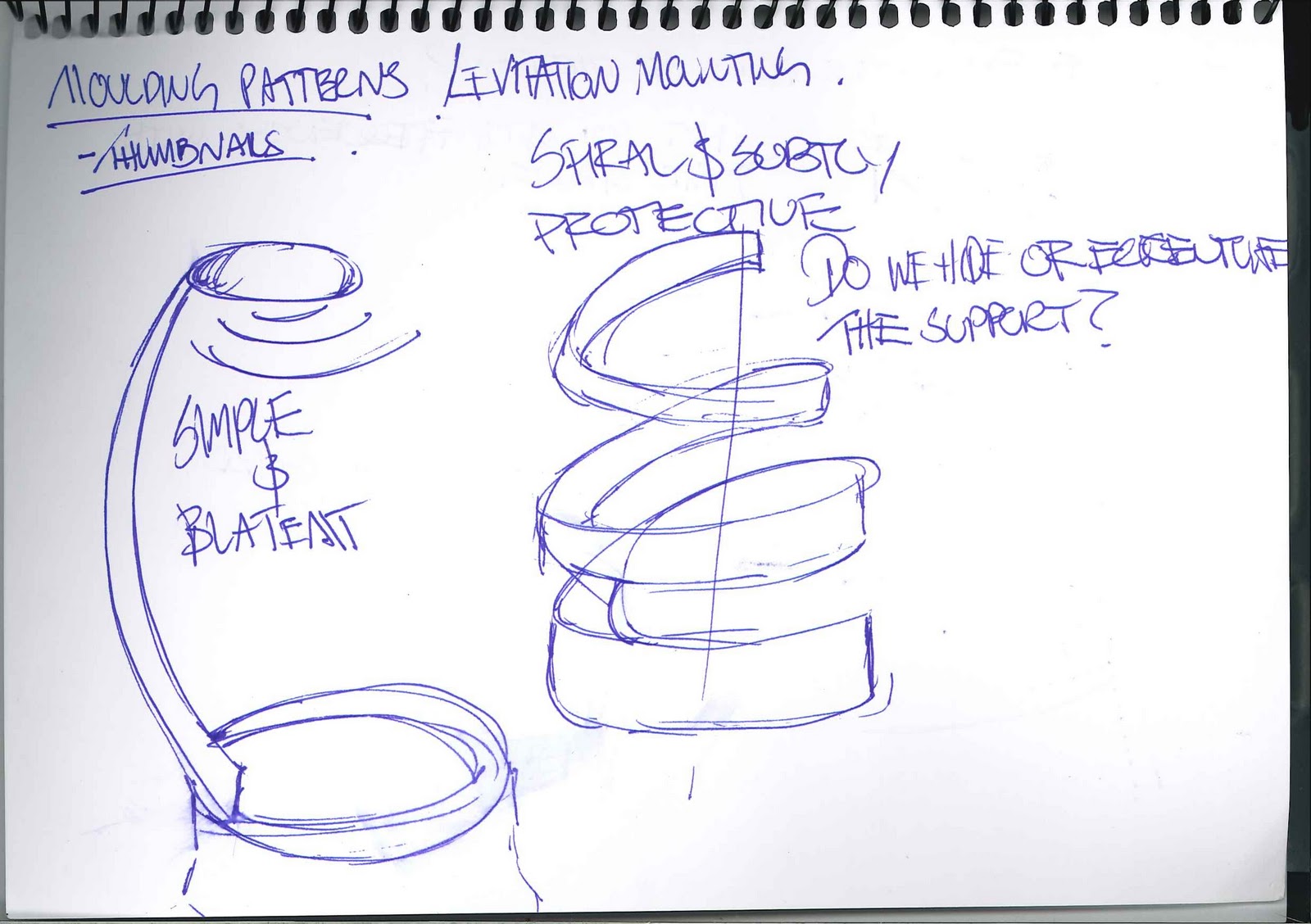
The following sketches show some form exploration as to how we can fit the product into the context as well as meet with the functional requirements:
Primarily the form will be following the function of the product as the system must work harmoniously to create the desired effects. However, these considerations must be taken to allow the products aesthetics to suitably fit into the context. To put this into a viable process, the main mechanisms will be modeled in CAD to allow for tolerances and allowances in the design.. so the form can then fit around these mechanisms to allow for a fully functional product without hindrances from the form.
As the main part of the product will be the base and the mechanism to allow the gas release, this will be modeled first to determine the approximate size that the overall product will need to be. After this has been completed and simulations have been run to determine feasibility of manufacturing as well as full functionality, the form will be modeled around this, with strong considerations into the environmental aesthetic appeal as well as the symbolism behind the from in its specific context.
For starters we need to consider our user, and what their collaborative or individual workspace might look like...
 |
| Image: Uni student work space |
So how can we fit our product into this context..?
The following sketches show some form exploration as to how we can fit the product into the context as well as meet with the functional requirements:
 |
| Sketch: Looking at how to incorporate the magnetic levitation into the clear outer casing |
 |
| Sketch: Incorporating the protection into the magnetic levitation support |
 |
| Sketch: Protection from flame as well as support??? |
 |
| Sketch: having the fan spin on top of the magnetic levitation rather than hang below??? |
As the main part of the product will be the base and the mechanism to allow the gas release, this will be modeled first to determine the approximate size that the overall product will need to be. After this has been completed and simulations have been run to determine feasibility of manufacturing as well as full functionality, the form will be modeled around this, with strong considerations into the environmental aesthetic appeal as well as the symbolism behind the from in its specific context.
Subscribe to:
Comments (Atom)